C:\1990S\WOLFENST.TXT
1992
Wolfenstein 3D: A Convincing World With Convenient Restrictions
Wolfenstein 3D turned a constrained grid world into a fast first-person view, making the geometry it could omit as important as the geometry it drew.
A first-person view has a demanding customer: the person holding the controls. Turn the camera and the walls need to move convincingly now. An impressive image delivered after the action has become irrelevant is a rather expensive postcard.
Wolfenstein 3D solved that problem with a useful agreement between the world and the renderer. The world supplied restrictions. The renderer used those restrictions to answer visibility questions quickly.
The result was a game in which movement through rooms and corridors felt immediate, even though the environment was far more constrained than a general three-dimensional scene. The interesting achievement lies in that combination of a convincing experience and a deliberately manageable representation.
A PC game in May 1992
The preserved Apogee/3D Realms publisher page gives May 5, 1992 as the original release date. It describes VGA graphics and a 286-or-better baseline. Its downloadable shareware episode is version 1.4, so the page’s detailed later requirements should not be treated as a byte-exact specification of the initial executable.1
This was id Software’s game, not the first first-person game. The publisher’s enthusiasm about spawning a genre is marketing language rather than a reason to erase earlier experiments.
John Carmack’s signed notes accompanying the later source release describe its ray-casting architecture and dynamically compiled scaling routines. They also identify taller walls, vertical motion and multiplayer as possible additions, rather than shipped capabilities.2
The surviving source is useful evidence about the machinery. It is later published material, not proof that every line exactly matches the first released build. Its availability also does not grant a blanket right to reproduce game artwork: the source distribution includes a Limited Use license.

John Carmack at GDC, March 11, 2010. Official GDC, source, CC BY 2.0. Commons version cropped in 2020; no additional alterations. Later photograph, not a 1992 exposure.

A plan can produce a perspective view
Begin with a top-down grid. Each cell says something about the space: an ordinary wall, an open area, or a special feature. The renderer must determine which wall a line of sight reaches first.
For a simple column of the image, cast a ray from the viewer into the map. Find its first wall intersection, then use that intersection to determine the wall column’s projected size and texture position.
Repeat for other viewing directions across the screen. The wall columns together form a perspective image. The map can remain two-dimensional while the display represents height and depth.
The surviving assembly code explicitly advances through vertical and horizontal grid intersections, tests map cells, handles hits, and proceeds to the next screen column. Separate paths handle doors and pushable walls.3 The grid is a useful organizing structure, not a claim that the whole environment is permanently static.
The following numerical example is original. It uses clean fractional coordinates and ordinary arithmetic to explain traversal. It does not reproduce the game’s fixed-point scale, angle table or actual map data.
Walk a ray through three crossings
Place the viewer at (1.5, 1.5) and choose a ray direction (1, 0.5). Parameter t controls how far we proceed along it:
The direction does not have unit length. That is fine for locating crossings as long as we do not mistake t for ordinary distance.
The first vertical grid line ahead is x = 2. Solving 1.5 + t = 2 gives t = 0.5. At that point, y = 1.75. The ray enters the cell just to the right of that boundary, cell (2, 1) in our zero-based grid.
The next horizontal boundary is y = 2. Solving 1.5 + 0.5t = 2 gives t = 1. The corresponding x coordinate is 2.5, so the ray enters cell (2, 2).
The next vertical boundary is x = 3. It occurs at t = 1.5, with y = 2.25. The ray enters cell (3, 2).
| Crossing | t | Position | Newly entered cell |
|---|---|---|---|
Vertical x = 2 | 0.5 | (2, 1.75) | (2, 1) |
Horizontal y = 2 | 1 | (2.5, 2) | (2, 2) |
Vertical x = 3 | 1.5 | (3, 2.25) | (3, 2) |
Let the first two cells be open and (3, 2) contain a wall. Traversal stops at the third crossing. Anything farther along that ray is hidden by the wall for this simple opaque-wall case.
The checker verifies the crossing values with exact fractions. It also confirms the order. Choosing the next boundary in order matters: checking a farther cell first could report a wall behind the one actually visible.
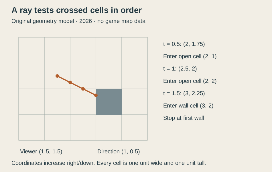
Original explanatory diagram, 2026. Viewer (1.5, 1.5), direction (1, 0.5) and wall cell (3, 2) reproduce the checked teaching example. Coordinates increase downward for this diagram; it is not game map data.
The regular grid removes unnecessary questions
For this direction, successive vertical crossings are separated by a change of 1 in t. Successive horizontal crossings are separated by 2 in t. Once the initial crossings are known, traversal can advance through these regular increments.
That structure is the point of using a grid. The renderer doesn’t need to test every wall in the map for every column. It follows the ray through the cells it reaches.
Our ray also avoids an exact corner crossing. A general implementation needs a rule when the vertical and horizontal crossings coincide, and must handle zero direction components and other quadrants. The clean example explains the main step without claiming those boundary cases disappear.
A useful model knows where it stops. We are checking the mathematics of one positive-direction ray, not writing an emulator or proving the complete original traversal correct.
The restrictions have another benefit: ordinary wall faces align with grid axes. Once a hit is known, the renderer has a convenient coordinate along that face from which to choose a texture column. In our example, the hit y coordinate has fractional part 0.25.
For an invented 64-column texture and an unflipped orientation, that fraction selects column 16. Actual orientation rules can flip or otherwise adjust the coordinate; 64 and the unflipped choice are explicit teaching assumptions here.
The texture gives the wall visual detail without requiring a separate geometric surface for each brick. Geometry locates the face; the image supplies the pattern on it.
Height needs forward depth
After finding the wall, the renderer still needs a projected height. With a fixed wall height and a chosen projection scale, the visible height varies inversely with forward depth.
For an arbitrary teaching scale of 240, a wall at forward depth 2 produces a height of 120 units. At depth 4, it produces 60. Twice as far ahead gives half the projected height.
The important word is forward. Raw distance along an oblique ray is not the same quantity.
Imagine a flat wall plane four units directly ahead of the camera. Its center lies at forward depth 4 and has ray distance 4. A point on that plane viewed at 30 degrees from the center has ray distance 4 / cos(30°), about 4.619, but the same forward depth.
Using raw ray distance would give that point a height of about 51.96 with our scale, instead of 60. Repeating the error toward the edges would make a flat wall appear distorted.
The surviving CalcHeight routine transforms the hit relative to the view and divides by its forward component. Actor transformation similarly distinguishes forward and lateral components.4 The worked numbers explain why that distinction matters; they are not literal game pixel heights.
Restrictions made room for the rest of the experience
The renderer’s wall model didn’t provide arbitrary slopes, stacked rooms or unconstrained vertical camera movement. Carmack’s later notes make clear that adding height variation would require changes to the texture mapper.
Enemies and items also needed representation. The surviving drawing code handles scaled actors separately from the wall traversal. Their screen position and size come from view-relative coordinates rather than making them additional grid-aligned wall faces.4
These divisions help explain how an environment can feel populated without requiring every visible thing to share the same geometry model. Different kinds of objects can have different representations, provided they cooperate in the final image.
The player experiences movement, visibility, opponents and feedback together. A restriction that remains unobtrusive during play can be an excellent engineering tradeoff, even if it looks severe on a feature checklist.
That tradeoff is contingent on hardware. Carmack’s retrospective notes describe scaling routines suited to uncached targets becoming troublesome on later cached processors. An optimization is a relationship with a machine, not a permanent badge attached to code.
A persuasive view from a tractable world
Wolfenstein 3D’s geometry is easier to admire once its limits are visible. A regular map makes traversal orderly. Fixed-height walls make column scaling manageable. Textures provide detail without multiplying the wall geometry. View-relative depth keeps the projection coherent.
The result gave the player a world they could navigate immediately. That immediacy depended on deciding which questions the renderer would be asked to answer.
General-purpose geometry would have expanded the environment’s possibilities and the implementation’s obligations. The shipped design made a narrower agreement and used it effectively.
A convincing interactive world doesn’t have to contain every kind of space. It has to behave convincingly in the spaces it offers, quickly enough that the next turn of the camera still feels like the player’s decision.
Footnotes
-
Apogee/3D Realms, preserved Wolfenstein 3D product page, original-release statement and version 1.4 download distinction. ↩
-
id Software, preserved source-release notes, Carmack’s retrospective comments, proposed changes and Limited Use license. Repository packaging note dated 2012 is not the game’s release date. ↩
-
id Software, surviving assembly traversal, grid intersection setup, core vertical/horizontal loop, next-column and special-wall paths actually read. ↩
-
id Software, surviving drawing code,
TransformActor,CalcHeightand scaling passages inspected. Examples are original, not copied code or benchmark results. ↩ ↩2